Free Shipping on Orders Above ₹499
Same Day Delivery Available in Pune & PCMC
Cash on Delivery (COD) Available
Read Our Shipping Policy
Free Shipping on Orders Above ₹499
Same Day Delivery Available in Pune & PCMC
Cash on Delivery (COD) Available
Read Our Shipping Policy

Light Sensor (LDR)
2 min read
In this project, we’ll learn how to use an LDR (Light Dependent Resistor) with an Arduino to detect light intensity.
An LDR is a sensor whose resistance changes depending on the amount of light falling on it:
- More light → lower resistance
- Less light → higher resistance
The Arduino reads these changing values and can use them to control other devices like LEDs, relays, buzzers, or automatic lights.
This project introduces the concept of:
- Analog Input
- Sensors
- Light Detection
- Voltage Divider Circuit
- Reading real-world data using Arduino
In simple words:
The Arduino can “sense” whether the environment is bright or dark by reading the LDR values.
Required Components #
- Arduino UNO × 1
- LDR (Light Dependent Resistor) × 1
- Resistor 10kΩ × 1 (for voltage divider)
- LED × 1 (any color)
- Resistor 220Ω × 1 (for LED)
- Breadboard × 1
- Jumper wires × several
Explanation #
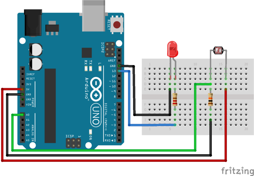
The LDR is connected in a voltage divider circuit along with a 10kΩ resistor.
One side of the LDR is connected to 5V.
The other side is connected to:
- Arduino analog pin A0
- 10kΩ resistor to GND
This arrangement creates a varying voltage depending on light intensity.
As the surrounding light changes:
- Bright light produces different voltage
- Darkness produces different voltage
The Arduino reads this voltage using: analogRead()
Unlike digital pins that read only HIGH or LOW, analog pins can read many values between 0 and 1023.
- 0 means very low voltage
- 1023 means maximum voltage
In this project:
- If the room becomes dark, the LED turns ON
- If the room becomes bright, the LED turns OFF
This is similar to automatic street lights.
Program #
int ldrPin = A0;
int ledPin = 13;

void setup()
{
    pinMode(ledPin, OUTPUT);
    Serial.begin(9600);
}

void loop()
{
    int ldrValue = analogRead(ldrPin);

    Serial.println(ldrValue);

    if(ldrValue < 500)
    {
        digitalWrite(ledPin, HIGH);
    }
    else
    {
        digitalWrite(ledPin, LOW);
    }

    delay(200);
}
Figure 1.2: LDR Program
Code Explanation #
Defining Pins :
int ldrPin = A0;
The LDR is connected to analog pin A0.
int ledPin = 13;
The LED is connected to pin 13.
Starting Serial Monitor :
Serial.begin(9600);
This allows the Arduino to send LDR values to the Serial Monitor.
You can see live sensor readings on your computer.
Reading LDR Value :
analogRead(ldrPin);
This reads the analog voltage from the LDR circuit.
The value will be between: 0 to 1023
Printing Sensor Values :
Serial.pringln(ldrValue);
Displays the sensor value on the Serial Monitor.
Condition Checking :
if(ldrValue < 500)
If the light level becomes low (darkness), the LED turns ON.
Otherwise, the LED remains OFF.
The value 500 is called a threshold value.
You can change it depending on your room lighting conditions.
Working Principle #
The LDR changes resistance according to light intensity.
This changing resistance changes the voltage in the circuit.
The Arduino reads this voltage and decides whether the environment is bright or dark.
Then it controls the LED accordingly.
In short:
- Dark environment → LED ON
- Bright environment → LED OFF
Real-Life Applications #
LDR sensors are used in many real electronic systems such as:
- Automatic street lights
- Solar garden lights
- Brightness control systems
- Mobile auto-brightness
- Camera light meters
- Smart home lighting
- Security systems
Beginner Tips #
- LDR values change depending on room lighting.
- If the LED behaves opposite, try changing the condition value.
- Use the Serial Monitor to observe live readings.
- Avoid loose connections on the breadboard.
- The threshold value may need adjustment for different environments.
✔ Challenges / Next Steps #
- Control multiple LEDs based on light level.
- Create an automatic night lamp.
- Use a relay to control AC bulbs.
- Display LDR values on an LCD.
- Use PWM to control LED brightness automatically.
- Build a sunlight tracking system.
Conclusion #
This project teaches how Arduino can read real-world sensor data using analog input.
You learned:
- How an LDR works
- How analog sensors work
- How Arduino reads varying voltages
- How automatic lighting systems work
This is an important step toward building:
- Smart automation systems
- IoT devices
- Environmental monitoring systems
- Sensor-based electronics projects
LDR projects are simple, useful, and widely used in real-world electronics.


