Free Shipping on Orders Above ₹499
Same Day Delivery Available in Pune & PCMC
Cash on Delivery (COD) Available
Read Our Shipping Policy
Free Shipping on Orders Above ₹499
Same Day Delivery Available in Pune & PCMC
Cash on Delivery (COD) Available
Read Our Shipping Policy

Basic Password Lock System
4 min read
In this project, we’ll build a simple password lock security system using a 4×4 matrix keypad, an I2C LCD display, and two LEDs.
The user enters a password using the keypad. The Arduino checks whether the entered password is correct.
- Correct Password → Green LED turns ON
- Incorrect Password → Red LED turns ON
The LCD displays messages such as:
- Enter Password
- Access Granted
- Access Denied
This project combines several important Arduino concepts into one practical application.
You will learn:
- Keypad Input
- I2C LCD Communication
- Password Verification
- LED Indicators
- User Interface Design
In simple words:
The keypad acts like a keyboard, the LCD acts like a screen, and the Arduino acts like a security guard checking the password.
Required Components #
- Arduino UNO × 1
- 4×4 Matrix Keypad × 1
- 16×2 I2C LCD Display × 1
- Green LED × 1
- Red LED × 1
- 220Ω Resistors × 2
- Breadboard × 1
- Jumper Wires × several
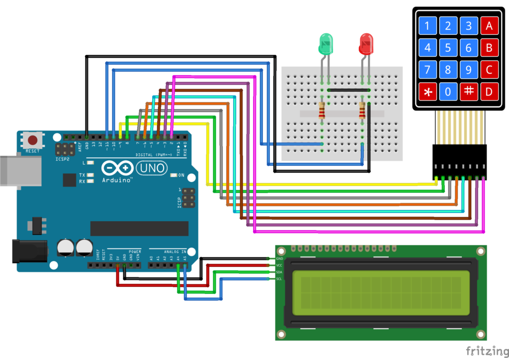
Connection Details #
I2C LCD Connections :
| LCD Pin | Arduino UNO |
|---|---|
| VCC | 5V |
| GND | GND |
| SDA | A4 |
| SCL | A5 |
Keypad Connections :
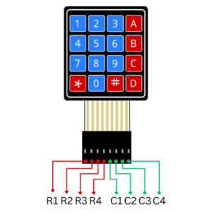
| Keypad Pin | Arduino Pin |
|---|---|
| R1 | 9 |
| R2 | 8 |
| R3 | 7 |
| R4 | 6 |
| C1 | 5 |
| C2 | 4 |
| C3 | 3 |
| C4 | 2 |
LED Connections : Green LED
| LED Pin | Connection |
|---|---|
| Long Leg (+) | Pin 10 through 220Ω resistor |
| Short Leg (-) | GND |
LED Connections : Red LED
| LED Pin | Connection |
|---|---|
| Long Leg (+) | Pin 11 through 220Ω resistor |
| Short Leg (-) | GND |
Explanation #
The keypad is used to enter a password.
Each key pressed is displayed as ” * ” on the LCD to hide the actual password.
The Arduino stores the entered keys and compares them with the predefined password.
If the password is correct:
- Green LED turns ON
- LCD displays “Access Granted”
If the password is incorrect:
- Red LED turns ON
- LCD displays “Access Denied”
After a few seconds, the system automatically resets and waits for a new password.
Required Libraries #
Install these libraries before uploading the code:
Keypad Library :
Search: " Keypad "
Install: Keypad by Mark Stanley and Alexander Brevig
LCD Library :
Search: “LiquidCrystal I2C "
Install: LiquidCrystal I2C by Frank de Brabander
Program #
This code creates a basic password lock system.
#include <Wire.h>
#include <LiquidCrystal_I2C.h>
#include <Keypad.h>

LiquidCrystal_I2C lcd(0x27, 16, 2);

const byte ROWS = 4;
const byte COLS = 4;

char keys[ROWS][COLS] =
{
  {'1','2','3','A'},
  {'4','5','6','B'},
  {'7','8','9','C'},
  {'*','0','#','D'}
};

byte rowPins[ROWS] = {9,8,7,6};
byte colPins[COLS] = {5,4,3,2};

Keypad keypad = Keypad(makeKeymap(keys), rowPins, colPins, ROWS, COLS);

String password = "1234";
String enteredPassword = "";

const int greenLED = 10;
const int redLED = 11;

void setup()
{
  pinMode(greenLED, OUTPUT);
  pinMode(redLED, OUTPUT);

  lcd.init();
  lcd.backlight();

  lcd.setCursor(0,0);
  lcd.print("Enter Password");
}

void loop()
{
  char key = keypad.getKey();

  if(key)
  {
    lcd.setCursor(enteredPassword.length(),1);
    lcd.print("*");

    enteredPassword += key;

    if(enteredPassword.length() == 4)
    {
      lcd.clear();

      if(enteredPassword == password)
      {
        lcd.print("Access Granted");

        digitalWrite(greenLED, HIGH);
        delay(3000);
        digitalWrite(greenLED, LOW);
      }
      else
      {
        lcd.print("Access Denied");

        digitalWrite(redLED, HIGH);
        delay(3000);
        digitalWrite(redLED, LOW);
      }

      enteredPassword = "";

      lcd.clear();
      lcd.print("Enter Password");
    }
  }
}
Figure 1.2: security system Program
Code Explanation #
Password Storage
String password = "1234";Stores the correct password.
You can change this value to any password you like.
Reading Keypad Input :
char key = keypad.getKey();Reads the pressed key from the keypad.
Hiding Password :
lcd.print("*");Displays an asterisk instead of the actual key.
This improves security.
Comparing Passwords :
if(enteredPassword == password)Checks whether the entered password matches the stored password.
Green LED :
digitalWrite(greenLED, HIGH);Turns ON when the password is correct.
Red LED :
digitalWrite(redLED, HIGH);Turns ON when the password is incorrect.
Working Principle #
User enters password using keypad.
Arduino stores the entered characters.
LCD displays ‘*’ for each key press.
Arduino compares entered password with stored password.
If correct:
- Green LED ON
- Access Granted
If incorrect:
- Red LED ON
- Access Denied
System resets and waits for another password.
Real-Life Applications #
This type of system is used in:
- Digital Door Locks
- Home Security Systems
- Office Access Control
- Hotel Room Locks
- ATM Machines
- Electronic Safes
- Smart Cabinets
- Industrial Security Systems
Beginner Tips #
- Verify the LCD I2C address (usually 0x27 or 0x3F).
- Check keypad wiring carefully.
- Use resistors with LEDs.
- Test the keypad separately before combining everything.
- Test the LCD separately before integrating the project.
✔ Challenges / Next Steps #
- Add a servo motor to lock/unlock a door.
- Add a buzzer for incorrect passwords.
- Store passwords in EEPROM.
- Add RFID authentication.
- Add fingerprint authentication.
- Display remaining attempts on LCD.
- Create a complete smart door lock system.
Conclusion #
This project combines three important Arduino modules into a practical security application.
You learned:
- How keypads work
- How LCD displays work
- How password verification works
- How to combine multiple modules in one project
This is an excellent beginner-to-intermediate project and serves as a foundation for advanced access control and smart security systems.


