Free Shipping on Orders Above ₹499
Same Day Delivery Available in Pune & PCMC
Cash on Delivery (COD) Available
Read Our Shipping Policy
Free Shipping on Orders Above ₹499
Same Day Delivery Available in Pune & PCMC
Cash on Delivery (COD) Available
Read Our Shipping Policy

Potentiometer
4 min read
In this project, we’ll learn how to use a potentiometer with Arduino to read variable analog values.
A potentiometer is a variable resistor that acts like a control knob. By rotating the knob, we can change the output voltage supplied to the Arduino.
The Arduino reads this changing voltage and converts it into a digital value that can be used in programs.
This project introduces important concepts like:
- Analog Input
- ADC (Analog to Digital Conversion)
- Variable Voltage
- Sensor Reading
- Serial Monitoring
In simple words:
The potentiometer works like a volume knob, and the Arduino reads its position as numbers.
Required Components #
- Arduino UNO × 1
- Potentiometer (10kΩ) × 1
- LED × 1 (Required for Upgraded Code)
- 220Ω Resistor × 1 (Required for Upgraded Code)
- Breadboard × 1
- Jumper Wires × several
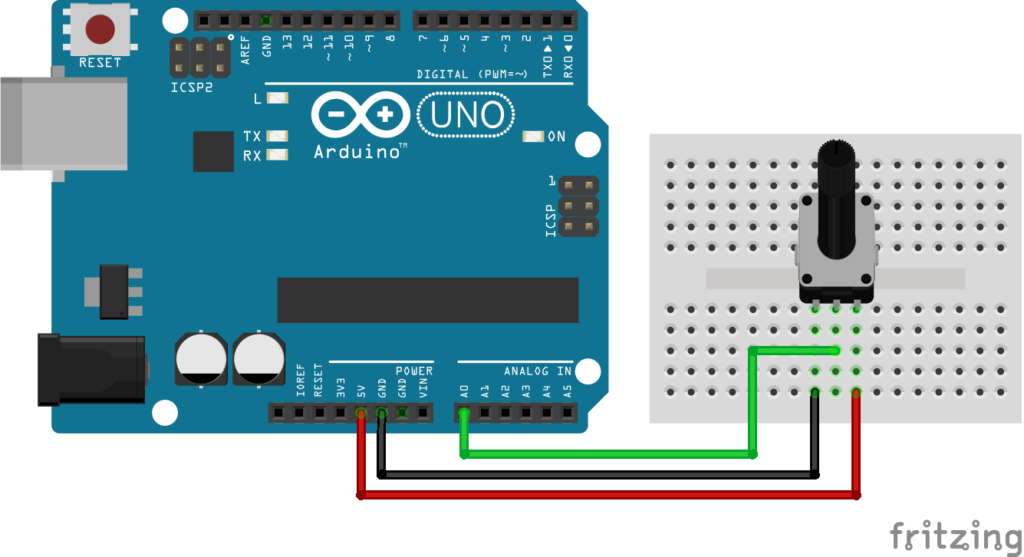
Potentiometer Connections #
| Potentiometer Pin | Connection |
|---|---|
| Left Pin | 5V |
| Middle Pin | A0 |
| Right Pin | GND |
The middle pin is called the Wiper Pin and provides the changing output voltage.
Explanation #
A potentiometer has three terminals.
The two outer pins are connected to:
- 5V
- GND
The middle pin provides a voltage that changes when the knob is rotated.
The Arduino reads this voltage using: analogRead();
The analog values range from:
| Voltage | Arduino Value |
|---|---|
| 0V | 0 |
| 5V | 1023 |
As the knob rotates:
- Voltage changes
- Arduino value changes
In simple words:
The Arduino converts the knob position into numbers between 0 and 1023.
Program #
This simple code reads the potentiometer value and displays it on the Serial Monitor.
int potPin = A0;

void setup()
{
    Serial.begin(9600);
}

void loop()
{
    int potValue = analogRead(potPin);

    Serial.print("Potentiometer Value: ");
    Serial.println(potValue);

    delay(200);
}
Figure 1.2: Potentiometer Program
Code Explanation #
Defining the Potentiometer Pin :
int potPin = A0;Stores the analog pin connected to the potentiometer.
Starting Serial Communication :
Serial.begin(9600);Allows Arduino to send data to the Serial Monitor.
Reading the Potentiometer :
analogRead(potPin);Reads the analog voltage from the potentiometer.
Displaying the Value :
Serial.println(potValue);Displays the value on the Serial Monitor.
You will see values changing between:
- 0
- 1023
depending on the knob position.
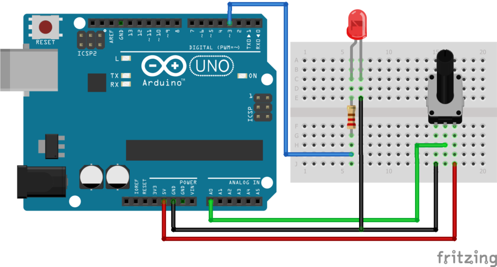
Upgraded Code #
| LED Pin | Connection |
|---|---|
| Long Leg (+) | Arduino PWM Pin 3 through 220Ω resistor |
| Short Leg (-) | GND |
Upgraded Code #
This upgraded version uses the potentiometer to control the brightness of an LED.
As the potentiometer rotates:
- LED brightness increases
- LED brightness decreases
const int potPin = A0;
const int ledPin = 3;

void setup()
{
    pinMode(ledPin, OUTPUT);
    Serial.begin(9600);
}

void loop()
{
    int potValue = analogRead(potPin);

    int brightness = map(potValue, 0, 1023, 0, 255);

    analogWrite(ledPin, brightness);

    Serial.print("Pot Value: ");
    Serial.print(potValue);

    Serial.print(" | Brightness: ");
    Serial.println(brightness);

    delay(100);
}
Figure 1.4: Upgraded version Potentiometer Program
Upgraded Code Explanation #
Reading the Potentiometer :
int potValue = analogRead(potPin);Reads the knob position.
Mapping Values :
map(potValue, 0, 1023, 0, 255);Converts the potentiometer value into a PWM brightness value.
Why?
Because:
- Potentiometer values = 0 to 1023
- PWM values = 0 to 255
Controlling LED Brightness :
analogWrite(ledPin, brightness);Adjusts the LED brightness according to the potentiometer position.
PWM Explanation #
PWM stands for Pulse Width Modulation.
Arduino rapidly switches the LED ON and OFF.
- More ON time → Brighter LED
- Less ON time → Dimmer LED
Our eyes see this as smooth brightness control.
Working Principle #
Simple Version :
- Rotate potentiometer
- Voltage changes
- Arduino reads the value
- Value appears on Serial Monitor
Upgraded Version :
- Rotate potentiometer
- Arduino reads the value
- Value is converted to PWM
- LED brightness changes accordingly
How to Test #
Simple Version :
- Upload the code.
- Open Serial Monitor in Arduino IDE.
- Set Baud Rate to
9600. - Rotate the potentiometer.
You will see values changing between 0 and 1023.
Upgraded Version :
- Connect the LED circuit.
- Upload the upgraded code.
- Rotate the potentiometer.
You will notice the LED brightness changing smoothly.
Real-Life Applications #
Potentiometers are commonly used in:
- Audio volume controls
- Fan speed regulators
- Light dimmers
- Display brightness controls
- Industrial control panels
- Laboratory equipment
Beginner Tips #
- Use a 10kΩ potentiometer for best results.
- The middle pin is always the output pin.
- Make sure the LED is connected to a PWM pin.
- Arduino UNO PWM pins are:
3, 5, 6, 9, 10, 11 - Always use a resistor with LEDs.
✔ Challenges / Next Steps #
- Control a servo motor using the potentiometer.
- Control RGB LED colors.
- Create a digital dimmer.
- Control motor speed.
- Build a menu navigation system.
- Display values on an LCD screen.
Conclusion #
This project teaches how Arduino reads analog inputs and uses them to control outputs.
You learned:
- How a potentiometer works
- How analog input works
- How PWM controls brightness
- How input and output interact
The potentiometer is one of the most useful components in electronics and is widely used in automation, control systems, and embedded projects.


