
No products in the cart.
Skip to main content

Micro Projects
Print
Sound Sensor Module
In this project, we’ll learn how to control an LED using a Sound Sensor Module and an Arduino UNO.
The sound sensor detects sounds such as clapping, speaking loudly, or tapping on a table. When the sound level exceeds a certain threshold, the sensor sends a signal to the Arduino.
In this project:
- A loud sound (such as a clap) turns the LED ON.
- Another loud sound turns the LED OFF.
This project introduces important concepts like:
- Sound Detection
- Digital Input
- LED Control
- Toggle Logic
- Conditional Statements (
if/else)
In simple words:
The sound sensor acts like an electronic ear. When it hears a loud sound, the Arduino changes the LED’s state.
Required Components
- Arduino UNO × 1
- Sound Sensor Module (Microphone Module) × 1
- LED × 1
- 220Ω Resistor × 1
- Breadboard × 1
- Jumper Wires × several
Circuit Diagram
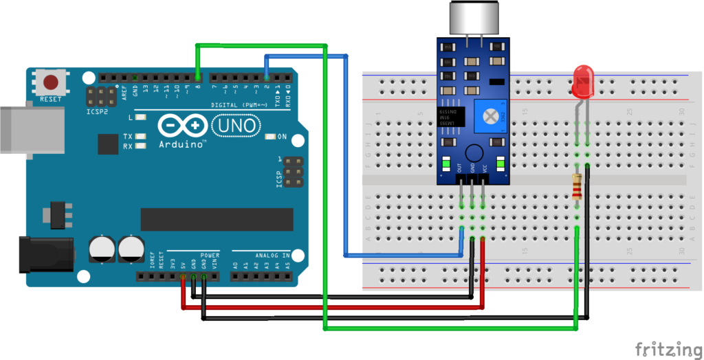
Figure 1.1: Sound sensor Circuit Diagram
Connection Details
Sound Sensor Module :
| Sensor Pin | Arduino UNO |
|---|---|
| VCC | 5V |
| GND | GND |
| DO (Digital Output) | D2 |
LED Connections :
| LED Pin | Arduino UNO |
|---|---|
| Long Leg (+) | Pin 8 through a 220Ω resistor |
| Short Leg (-) | GND |
Explanation
The sound sensor module contains:
- A microphone
- An amplifier
- A comparator circuit
- A sensitivity adjustment potentiometer
The microphone converts sound waves into electrical signals. The comparator checks whether the sound level is above the threshold set by the potentiometer.
When a loud sound is detected:
- The DO pin changes its output state.
- The Arduino reads this signal.
- The LED changes between ON and OFF.
In simple words:
The sound sensor listens for loud sounds. Every time it hears one, the Arduino changes the LED from OFF to ON or from ON to OFF.
Program
This simple code turns the LED ON while a loud sound is detected and turns it OFF when the sound stops.
⚙️
Sound.ino
Copy
const int soundPin = 2;
const int ledPin = 8;

void setup()
{
  pinMode(soundPin, INPUT);
  pinMode(ledPin, OUTPUT);
}

void loop()
{
  int soundState = digitalRead(soundPin);

  if(soundState == LOW)    // Most modules are active LOW
  {
    digitalWrite(ledPin, HIGH);
  }
  else
  {
    digitalWrite(ledPin, LOW);
  }
}
Figure 1.2: Sound sensor Program
Code Explanation
Defining the Pins :
const int soundPin = 2;
const int ledPin = 8;
These variables store the Arduino pins connected to the sound sensor and LED.
Reading the Sound Sensor :
int soundState = digitalRead(soundPin);Reads the digital output from the sound sensor module.
Turning the LED ON :
digitalWrite(ledPin, HIGH);Turns the LED ON when a loud sound is detected.
Turning the LED OFF :
digitalWrite(ledPin, LOW);Turns the LED OFF when no loud sound is detected.
Upgraded Code
This upgraded version uses toggle logic.
- First clap → LED ON
- Second clap → LED OFF
- Third clap → LED ON
- And so on…
A short delay is included to prevent multiple triggers from a single clap.
⚙️
Upgraded-Code.ino
Copy
const int soundPin = 2;
const int ledPin = 8;

bool ledState = false;
bool lastSoundState = HIGH;

void setup()
{
  pinMode(soundPin, INPUT);
  pinMode(ledPin, OUTPUT);
}

void loop()
{
  bool currentSoundState = digitalRead(soundPin);

  // Detect a new sound event (HIGH to LOW transition)
  if(lastSoundState == HIGH && currentSoundState == LOW)
  {
    ledState = !ledState;
    digitalWrite(ledPin, ledState);

    delay(300); // Ignore repeated triggers from the same clap
  }

  lastSoundState = currentSoundState;
}
Figure 1.3: Upgraded version of Sound sensor Program
Upgraded Code Explanation
Storing the LED State
bool ledState = false;Keeps track of whether the LED is currently ON or OFF.
Detecting a New Sound :
if(lastSoundState == HIGH && currentSoundState == LOW)Detects only the moment when a new sound is received, preventing continuous triggering while the sound is still present.
Toggling the LED :
ledState = !ledState;Reverses the LED state:
- OFF → ON
- ON → OFF
Preventing Multiple Triggers :
delay(300);Ignores additional sound pulses from the same clap for a short time.
Working Principle
- The microphone listens for sound.
- The comparator checks if the sound is louder than the set threshold.
- The module changes the DO output.
- The Arduino reads the signal.
- The LED changes its state based on the program logic.
How to Test
Simple Version
- Upload the code.
- Adjust the sensor’s blue potentiometer.
- Clap your hands near the microphone.
- The LED should turn ON.
- When the sound stops, the LED should turn OFF.
Upgraded Version
- Upload the upgraded code.
- Adjust the sensor sensitivity.
- Clap once.
- The LED should turn ON.
- Clap again.
- The LED should turn OFF.
- Repeat to toggle the LED.
Troubleshooting
✔ LED Never Turns ON :
- Check the sensor wiring.
- Verify the LED polarity.
- Increase the sensor sensitivity using the blue potentiometer.
- Make sure the LED is connected to pin D8.
✔ LED Stays ON All the Time :
- Reduce the sensor sensitivity by adjusting the potentiometer.
- Move away from noisy environments.
- Check whether your sound sensor outputs LOW when sound is detected. Some modules use HIGH instead. If your module is active HIGH, change the condition in the code accordingly.
✔ LED Flickers Randomly :
- Reduce the sensor sensitivity.
- Avoid placing the sensor near speakers or fans.
- Ensure all jumper wire connections are secure.
Real-Life Applications
Sound sensor modules are commonly used in:
- Clap Switches
- Sound-Activated Lights
- Smart Home Projects
- Noise Monitoring Systems
- Alarm Systems
- Interactive Toys
- Voice-Activated Demonstrations
- Educational Electronics Projects
Beginner Tips
- Adjust the blue potentiometer until the sensor reliably detects claps.
- Test in a quiet room for the best results.
- Use short, sharp sounds like claps for more consistent detection.
- Keep the microphone free from dust and obstructions.
- Remember that the DO pin only detects whether the sound crosses a threshold. If you want to measure sound intensity, use the AO (Analog Output) pin instead.
✔ Challenges / Next Steps
- Display sound detection on an I2C LCD.
- Add a buzzer for sound alerts.
- Count the number of claps using the Serial Monitor.
- Control multiple LEDs with different clap patterns.
- Build a clap-controlled home automation system.
- Create a simple sound level indicator using the analog output.
Conclusion
This project demonstrates how to use a Sound Sensor Module with an Arduino UNO to control an LED.
You learned:
- How a sound sensor detects loud sounds.
- How to read a digital sensor input.
- How to control an LED based on sound.
- How to implement toggle logic using a clap.
This is a fun beginner project that introduces event-based programming and can be expanded into more advanced sound-controlled automation systems.
Table of Contents
